 can
be combined with selectors of different operating positions, sizes, and
current carrying capacity. Such a modular construction principle enables
to offer a Transformer user the most appropriate Tapchanger for each application.
can
be combined with selectors of different operating positions, sizes, and
current carrying capacity. Such a modular construction principle enables
to offer a Transformer user the most appropriate Tapchanger for each application.The type PG is a double compartment Tapchanger, with a Divertor Switch,
and a Tap Selector. The design is based on modular principle, so that divertors
of various voltages and current ratings can
be combined with selectors of different operating positions, sizes, and
current carrying capacity. Such a modular construction principle enables
to offer a Transformer user the most appropriate Tapchanger for each application.
The Tapchanger type PG is available in single phase, two phase and three
phase executions. Since the tap selector does not make, or break current,
it can be built into the main Transformer tank as part of core and coil
assembly. This avoids the necessity of taking high voltage tapping leads
out of the Transformer tank, through a Terminal barrier board. 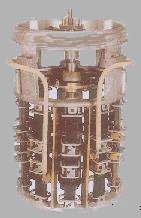
The tapchanger is available with insulation against ground to suit service voltage from 33kV to 245kV. The basic current rating of the Divertor Switch is 200A and 400A.
The Tapchanger is driven by an external driving mechanism, through a system of horizontal, and vertical driving shafts, interconnected by a Bevel Gear. The mechanism box and the Bevel Gear are to be mounted by the Transformer Manufacturer on his Transformer tank.
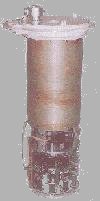
The Divertor Switch is arranged in the form of a removable insert, which fits into a fixed, insulated, oil tight Divertor Oil Vessel. The Tap Selector hangs below the Divertor Oil Vessel, with an intervening gear box, which houses a Geneva mechanism for driving the Tap Selector.
The Divertor Oil Vessel itself suspended from a steel Tapchanger Head, which is to be mounted on the roof plate of the Transformer, with a gasket. The Divertor Insert is lowered into the Divertor Oil Vessel through a top opening, which is then sealed by an Insert cover plate of steel.
The Divertor Insert is driven by an insulated drive tube housed within the Divertor Oil Vessel. At the top end, this insulated drive tube couples to the output of a worm reduction gear, mounted on the Insert Cover Plate. The worm reduction gear itself obtains its drive from the driving mechanism. At the bottom end, the divertor drive tube extends into the Tap Selector gear box through an oil tight gland. The divertor drive tube, in addition to charging up the stored energy unit mounted on top of the divertor switch, also serves to drive the selector. A mechanical tap position indicator provided on top of the insert is visible through a glass window even when the Tapchanger head cover is in position, so that the position of the Tap Selector can be viewed without opening the insert cover. The mechanical indication device is reproduced at the bottom of the Divertor Oil Vessel also, so that when the insert is taken out, say for inspection, the position of the Tap Selector can still be ascertained. Leads from the Divertor are taken into the Selector space through oil tight bushings, mounted on the flat machined surface of the Divertor bottom flange. Thus, there are no holes on the cylindrical surface of the Divertor Oil Vessel, which are technically difficult to seal against Oil leakage.
The Tap Selector, which is suspended from Divertor Vessel bottom flange, can be equipped with 10, 12, 14, 16, or 18 operating positions for linear tapping regulation. It is also possible to provide the Tap Selector with a Pre Selector, which can be either a Coarse/Fine, or Reversing Switch. Thus a maximum of 35 positions are possible. The selector is available in 4 different sizes, each size corresponding to different levels of voltage withstand between the various live electrical parts of the selector. Choice of Tap Selector size depends on the various voltages between live parts that the Transformer Designer expects in a particular application. Any of the four sizes of the Selector can be used with any level of voltage withstand against ground, the latter being a function only of the Divertor Oil Vessel insulation strength, and not a function of the Selector. A positive central drive, combined with a Geneva mechanism mounted between the Divertor and the Selector, ensures positive positioning of the moving contacts. Contacts are very generously designed, so as to obtain low temperature rise, keeping in mind that the Selector is intended to operate through out the life of the Transformer without any inspection.
The Tapchanger is supplied complete with a motor drive, which is common to all the three phases in case of an application involving three single units, e.g. 132kV Line End Tapchangers. OLG's scope of supply includes necessary horizontal, and vertical external drive shafts, and the coupling Bevel Gear. Coupling shafts are provided with a device to lengthen or shorten the length of the shafts, a feature which makes insertion of shafts between heavy fixed parts simple. The drive mechanism is housed in a sheet steel cabinet with a lift off door. Flanged drive motor upto 3HP size can be accommodated, as required for the largest Tapchangers. The mechanism in its standard execution offers one dial switch for remote indication, a local Tap Number Indicator, one mechanical wheel for observing tap change in progress, Tapchanger in Progress Switch, limit switches for cutting off the motor at end positions, operation counter, and Hand Drive for emergency Operations. A window on the door indicates the mechanical tap position, and the operation counter, without need to open the door. A great speciality in the design is that the end position mechanical release is based on the differential gear principle, and does not involve shear pins, or mechanical blockage, of the drive system.
Since the design is of a modular concept, many different versions are possible, with the same basic units, the overall dimensions will depend on individual application. Therefore, OLG will be pleased to supply you individual dimensioned General Arrangement drawings, to suit your requirements.